Why is my GBC Velobind System 3 not working?
LED List for Troubleshooting:
The following LEDs will help you in the troubleshooting steps listed below.
- L1 = HEAT LED
- L2 = PUNCH MOTOR LED
- L3 = DEBIND LED
- L4 = BIND LED
WARNING: Always unplug the machine to avoid possible severe electrical shock before attempting any repairs. Our Service Techs are ready to come to your location and fix your machine. Call us at 1-866-455-9900 to get a quote or ask questions!

Need a Service & Repair Technician to come and fix your Velobind System 3 on site? View our Service & Repair to get a quote & parts info.
Need supplies to bind with your Velobind System 3? Check out our Velobind Strips, Binding Covers, and Velobind Machines to see our full selection.
Troubleshooting:
Possible Causes & Fixes:
- Bind Timing Switch (S13) out of adjustment or defective. - Adjust/replace Bind Timing Switch (9779311 - Switch and 9776353 - Actuator).
- Pressure Bar Racks or Pinion Gears jammed with debris. - Check Racks and Gears for pieces of paper or plastic and clean.
- Pressure Bar Racks uneven. - Remove Pressure Bar and check/replace Racks (9779044).
- Roll Pin may be broken, or have fallen out of Pinion Gear(s). - Reinstall/replace Roll Pin (9778665 - Call 1-866-455-9900).
- Drive Gear or Drive Arm may be broken or have broken teeth. - Replace Drive Gear (9778116), Drive Arm (9776394), and Brass Link (9778467).
- Drive Arm Roller may be too high or too low. - Adjust Drive Arm Roller as needed.
- Pressure Bar Racks may be broken. - Replace Racks (9779044).
- Pressure Bar may be broken. - Replace Pressure Bar (9781324).
- Trunnion may be loose. - Replace w/Trunnion Kit (9776337).
- Pawl Spring out of adjustment or defective. - Adjust/replace Pawl Spring (9779280) as needed.
- Drive Gear and Drive Arm not meshing due to Side Plate Tab out of adjustment. - Adjust Side Plate Tab (where Drive Arm comes to rest) up to raise Pressure Bar higher.
- Screw out of Pressure Bar, or Linkage loose. - Reinstall Pressure Bar Screw and/or tighten Linkage hardware.
- Pressure Bar Switch (S11) defective. - Replace Pressure Bar Switch Assembly (9780089).
- Pressure Bar Harness may be defective. - Replace Pressure Bar Switch Assembly (9780089).
- Bind Motor may be defective. - Replace Bind Motor (9778565).
- P.C. Board may be defective. - Replace P.C. Board (9783672).
Technician Notes:
Velobind System 3 Pro stays in stand by mode. Installed Cut-Off Thermostat (PTGBC-9781812) and Pro Punch Thermistor (PTGBC-9781354).
Possible Causes & Fixes:
- Power Cord not plugged into wall socket or Receptacle at Base of machine. - Make sure Power Cord is plugged into wall socket and Receptacle in rear base of machine.
- Machine not turned on. - Make sure "On" Button is depressed.
- Blown Fuse on P.C. Board. - Check/replace Fuse (9781859 - 115 VAC or 9781860 - 240 VAC) on P.C. Board.
- Debris Tray not fully inserted into base. - Make sure Debris Tray is inserted all the way into Base.
- Power Cord defective. - Check/replace Power Cord (9781344 - 115VAC or 9781345 - 240VAC). Call 1-866-455-9900 for power cord replacements info.
- Broken Receptacle in rear Base of machine. - Check/replace Receptacle.
- Broken Wire(s), loose Wiring Connections. - Check for defective Wiring, or loose Wiring Connections.
- Defective P.C. Board. - Check if LED "L1" lights: if it does, check Heaters (9778217 - Upper Heater or 9778226 - Lower Heater) for 18 ohms together, 36 ohms each, and replace as needed; if it doesn't, problem with P.C. Board (9783672).
- Connectors on P.C. Board connected backwards. - Check orientation of Connectors, and reinstall as needed.
Possible Causes & Fixes:
- Defective P.C. Board or Punch Motor Assembly. - Check if LED "L2" lights: if it does, check/replace Punch Motor (9778567 - 115VAC or 9778568 - 240VAC) and replace if needed; if it doesn't, possible problem with P.C. Board (9783672).
- Defective Capacitor. - Check/replace Capacitor (9776779 - 115VAC or 9776780 - 240VAC). Call 1-866-455-9900 for these parts.
- Broken Wire(s), loose Wiring Connections. - Check for defective Wiring or loose Wiring Connections.
- Punch Assembly jammed with debris or plastic. - Clean out Punch throat and die holes - replace defective Punch Housing (9778638 - VeloBind (Call 1-866-455-9900) or 9781804 - SureBind) if needed.
- Loose or defective Punch Motor Brake Hub - Tighten/replace Punch Motor Brake Hub (9776308).
- Broken Punch Actuator Tabs. - Replace Punch Actuator (9776364 - VeloBind (Call 1-866-455-9900) or 9781390 - SureBind).
- Punch Timing Switch (S8) may be defective, or out of adjustment. - Adjust per instructions on Section 6.1, or replace Punch Timing Switch (9779311 - Switch and 9776354 - Actuator).
- Punch Assembly jammed. - Remove Punch Links, and check Actuator and Pin travel.
Possible Causes & Fixes:
- Broken Wire(s), loose Wiring Connections. - Check for loose Wiring Connections, or defective Wiring.
- Punch Timing Switch (S8) may be out of adjustment or broken. - Adjust per instructions on Section 6.1, or replace Punch Timing Switch (9779311 - Switch and 9776354 - Actuator)
- Defective P.C. Board or Punch Motor Assembly. - Check if LED "L2" lights: if it does, check/replace Punch Motor (9778567 - 115VAC or 9778568 - 240VAC) and replace if needed; if it doesn't, possible problem with P.C. Board (9783672).
- Auto Punch Switch (S4) defective, or out of adjustment. - Adjust/replace Auto Punch Switch (9779325 - Call 1-866-455-9900).
Possible Causes & Fixes:
- Punch Timing Switch (S8) may be out of adjustment. - Adjust per instructions on Section 6.1, or replace Punch Timing Switch (9779311 - Switch and 9776354 - Actuator)
- Defective P.C. Board or Punch Motor Assembly. - Check if LED "L2" lights: if it does, check/replace Punch Motor (9778567 - 115VAC or 9778568 - 240VAC) and replace if needed; if it doesn't, possible problem with P.C. Board (9783672).
Possible Causes & Fixes:
- Loose Wire on Capacitor - causes Motor to reverse polarity. - Check all Wires and Connections on Capacitor.
Possible Causes & Fixes:
- Worn Punch Links. - Replace Punch Links (9778461) as needed.
- Punch Pins may be dull or burred. - Replace Punch Pins (9778684) as needed.
- May be using surface coated, or treated paper. - This type of paper will cause excessive squeaking or noise.
- Punch Motor may be defective. - Check and Replace Punch Motor (9778567 - 115VAC or 9778568 - 240VAC).
- Insufficient lubrication between Punch Actuator and Housing, or on Punch Links, or Punch Motor Cranks. - Lubricate these areas as needed.
- Punch Motor Brake may be defective. - Replace Punch Motor Brake Hub (9776308).
Possible Causes & Fixes:
- Internal Thermal Cutoff shuts down Punch Motor to keep from overheating. - After approximately 20 minute cool down period, you can resume punching. Recommend punch and bind cycle instead of continuously punching for long periods.
Possible Causes & Fixes:
- Punch Timing Switch (S8) defective, or out of adjustment. - Adjust per instructions on Section 6.1, or replace Punch Timing Switch (9779311 - Switch and 9776354 - Actuator).
- Check for loose or defective Punch Motor Brake Hub. - Tighten/replace Punch Motor Brake Hub (9776308).
- Punch Brake Solenoid may be defective. - Replace Punch Brake Solenoid (9776316 - 115VAC or 9776317 - 240VAC (1132609 240VAC).
- Punch Motor Brake Lever may be worn, or broken. - Replace Punch Motor Brake Lever (9776310 / 1132606).
- Broken Wire(s), loose Wiring Connections. - Check for defective Wiring, or loose Wiring Connections.
- Check for loose or broken Punch Cam. - Tighten/replace Punch Cam (9781677).
- Punch Motor may be defective. - Check and Replace Punch Motor (9778567 - 115VAC or 9778568 - 240VAC).
- Check for worn Punch Links. - Replace Punch Links (9778461) as needed.
Possible Causes & Fixes:
- Punch Throat has debris, pins, or strip stuck in Throat. - Check and clean Punch Throat.
- Punch Edge Guide out of adjustment. - Adjust and check per Operator Instructions for Binding on page 4-5.
- Punch Tabs may be out of adjustment. - Carefully adjust Punch Tabs as needed with a Flat Blade Screwdriver.
- Not inserting paper squarely into Punch Throat. - Make sure to insert paper squarely into Punch Throat.
Possible Causes & Fixes:
- Punch Assembly jammed, or Punch Throat has debris, pins, or strip stuck in Throat. - Remove Punch Links, and check Actuator and Pin travel, and clean Punch Throat.
- Remove Punch Links, and check Actuator and Pin travel, and clean Punch Throat. - Tighten/replace Punch Motor Brake Hub (9776308).
- Punch Pins may be dull or burred. - Replace Punch Pins (9778684) as needed.
- Punch Timing Switch (S8) out of adjustment or broken. - Adjust per instructions on Section 6.1, or replace Punch Timing Switch (9779311 - Switch and 9776354 - Actuator).
- Punching too much paper at one time. - Make sure not to punch more than 25 sheets of 20 pound bond paper, 3 sheets of plastic, or 4 covers in one session.
- Punch Housing biased too high - Pins hanging down. - Loosen Punch Housing Mounting Bolts, and bias Punch Housing down enough to prevent Punch Pins from hanging down.
Possible Causes & Fixes:
- Punch Actuator may be broken or warped. - Replace Punch Actuator (9776364 - VeloBind (Call 1-866-455-9900) or 9781390 - SureBind).
- Check for elongated Punch Housing Die Holes. - Replace defective Punch Housing (9778638 - VeloBind (Call 1-866-455-9900) or 9781804 - SureBind) if needed.
- Punch Pins may be dull or burred. - Replace Punch Pins (9778684) as needed.
- Punch Actuator Tabs may be broken. - Replace Punch Actuator (9776364 - VeloBind (Call 1-866-455-9900) or 9781390 - SureBind).
- Punch Link Bearings may be worn (out of round). - Replace Punch Links (9778461) as needed.
- Punch Die Holes may be plugged with debris. - Clean out Punch Die Holes.
- Punch Pins may be hanging down - Punch Housing biased too high. - Loosen Punch Housing Mounting Bolts, and bias Punch Housing down enough to prevent Punch Pins from hanging down.
- May be using surface coated or treated paper. - This type of paper does not always punch clean.
Possible Causes & Fixes:
- Transformer on P.C. Board may be defective. - Replace P.C. Board (9783672).
- "On" Button not pressed. - Depress "On" Button.
- Power Cord not plugged into rear of Base or wall socket. - Check Power Cord to be sure it is plugged into wall Socket and Receptacle in rear Base of machine.
- Panel Switch Membrane or LED P.C. Board defective. - Replace Panel Switch Membrane (9784010 - Call 1-866-455-9900) or LED P.C. Board (9784009).
- Defective 10/5 Amp Fuse on P.C. Board. - Replace Fuse (9781859 - 10 Amp or 9781860 - 5 Amp).
Possible Causes & Fixes:
Possible Causes & Fixes:
- Broken Wire(s), or loose Wiring Connections. - Check for defective Wiring, or loose Wiring Connections.
- P.C. Board may be defective - Replace P.C. Board (9783672).
Possible Causes & Fixes:
- P.C. Board may be defective. - Replace P.C. Board (9783672).
Possible Causes & Fixes:
- Thermistor may be defective. Should read 1 Megaohm +20% cold. - Replace Thermistor (9781354).
- Temperature may need to be adjusted higher. - Adjust on Switch Panel per instructions on Section 6.6.
- Broken Wire(s), or loose Wiring Connections. - Check for defective Wiring, or loose Wiring Connections.
- Check for defective Heaters. - Check resistance of Heaters for approximately 36 ohms each, and 18 ohms in parallel, and replace Heaters (9778217 - Upper Heater and 9778226 - Lower Heater).
- P.C. Board may be defective. - Replace P.C.B. (9783672).
Possible Causes & Fixes:
- Cutoff Thermostat may be defective. - Replace Cutoff Thermostat (9781812).
- Thermistor may be defective. Should read 1 Megaohm +20% cold. - Replace Thermistor (9781354).
- See if LED "L1" lights on P.C. Board; if it does, check for defective Heater(s); if it doesn't, defective P.C. Board. - Check resistance of Heaters for approximately 36 ohms each, and 18 ohms in parallel, and replace Heaters (9778217 - Upper Heater and 9778226 - Lower Heater), or replace P.C. Board (9783672).
- Broken Wire(s), or loose Wiring Connections. - Check for loose Wiring Connections, or defective Wiring.
Possible Causes & Fixes:
Possible Causes & Fixes:
- Bind Timing Switch (S13) defective, or may be out of adjustment. - Adjust per instructions on Section 6.2, or replace Bind Timing Switch (9779311 - Switch and 9776354 - Actuator).
- Pressure Bar Switch (S11) may be defective or broken. - Replace Pressure Bar Switch Assembly (9780089).
- See if LED "L6" lights: if it does, Bind Motor may be defective. - Replace Bind Motor (9778565).
- Pressure Bar Harness may be defective. - Replace Pressure Bar Switch Assembly (9780089).
- Bind Motor Pulley may be broken, causing Drive Belt to come off. - Replace Bind Motor Pulley (9778704).
- Broken Wire(s), or loose Wiring Connections. - Check for defective Wiring, or loose Wiring Connections.
- Pressure Bar Switch Actuator behind or in front of top strip - not being actuated. - Instruct operator to stack document against Backstop and next to Bind Guide, so that Pressure Bar is lowered on document and top strip correctly.
- See if LED "L6" lights: if it doesn't, P.C. Board may be defective. - Replace P.C. Board (9783672).
Possible Causes & Fixes:
- Pressure Bar Switch (S11) may be defective. - Replace Pressure Bar Switch Assembly (9780089).
- Bind Timing Switch (S13) may be defective, or out of adjustment. - Adjust per instructions on Section 6.2, or replace Bind Timing Switch (9779311 - Switch and 9776354 - Actuator).
- Drive Arm or Drive Gear may be broken, or have broken teeth. - Replace Drive Gear (9778116), Drive Arm (9776394), and Brass Link (9778467).
- Trunnion may be loose. - Replace with Trunnion Kit (9776337).
- Broken Wire(s), or loose Wiring Connections. - Check for defective Wiring, or loose Wiring Connections.
- Pressure Cams may be worn - timing cannot be adjusted properly. - Replace Pressure Cams (9776959).
Possible Causes & Fixes:
- Extruder Spring may be broken. - Replace Extruder Spring (9779260).
- Pawl Spring may be bent or improperly attached. - Adjust/replace Pawl Spring (9779280) as needed.
- Cooling Fingers may be broken or stuck down (check for cut off pins caught in Cooling Fingers). - Replace Cooling Finger(s) (9778687).
- Check temperature - may be too hot or cold. - Adjust per instructions on Section 6.6.
- Knife Blade may be out of adjustment, or Teflon worn off. - Adjust per instructions on Section 6.7, or replace Blade (9776713 - VeloBind or 9781601 - SureBind) per instructions on Section 6.10.7.
Possible Causes & Fixes:
- Thermistor may be defective. Should read 1 Megaohm +20% cold. - Replace Thermistor (9781354).
- Check for plastic build up on Knife Blade, due to Teflon worn. - Replace Blade (9776713 - VeloBind or 9781601 - SureBind) per instructions on Section 6.10.7.
- Temperature too high. - Adjust on Switch Panel per instructions on Section 6.6.
Possible Causes & Fixes:
- Knife Blade may be out of adjustment, or Teflon worn off. - Adjust per instructions on Section 6.7, or replace Blade (9776713 - VeloBind or 9781601 - SureBind) per instructions on Section 6.10.7.
- Check for worn Cams, or Cam Followers. - Replace Cams (9776840/9781757 - Cutter; 9776841 - Extruder; 9779865 - Cooling (Call 1-866-455-9900); 9779084 - Followers).
- Cooling Fingers may be broken or stuck down (check for cut off pins in Cooling Fingers). - Replace Cooling Finger(s) (9778687).
- Flat Springs may be broken or defective. - Replace Flat Springs (9779263).
- Check for plastic build up on Blade due to Teflon being worn. - Replace Blade (9776713 - VeloBind or 9781601 - SureBind) per instructions on Section 6.10.7.
- Extruder Spring may be broken. - Replace Extruder Spring (9779260).
- Blade Retaining Nuts not tight. - Tighten Retaining Nuts.
- Pawl Spring may be bent or improperly attached. - Adjust/replace Pawl Spring (9779280) as needed.
- Cooling Bracket Screws to Cooling Finger Assembly may be loose. - Tighten Screws.
- May be missing Locating Pin. - Please follow the binding instructions in your machine manual (Please call us at 1-866-455-9900 if you don't have it).
- Knife Blade or Knife Support may be warped. - Replace Blade (9776713 - VeloBind or 9781601 - SureBind) per instructions on Section 6.10.7 or Support (9776705).
Possible Causes & Fixes:
- See if LED "L7" lights: if it does, Bind Motor may be defective; if it doesn't, P.C. Board may be defective. - Replace Bind Motor (9778565) or P. C. Board (9783672).
- Pressure Bar Switch (S11) may be defective. - Replace Pressure Bar Switch Assembly (9780089).
- Bind Timing Switch (S13) may be out of adjustment or defective. - Adjust per instructions on Section 6.2, or replace Bind Timing Switch (9779311 - Switch and 9776354 - Actuator).
Possible Causes & Fixes:
- See if LED "L7" lights: if it does, then Bind Motor is okay; if it doesn't, then defective component on P.C. Board. - Replace Bind Motor (9778565) or P. C. Board (9783672).
- See if LED "L7" lights: if it doesn't, then problem with membrane switch; if it does, then problem with transformer on P.C.B. (check for 16 volts coming out of 16 volt side). - Replace Membrane Switch (9784010 - Call 1-866-455-9900) or P.C.B. (9783672).
- Extruder Spring may be broken, or disconnected. - Replace Extruder Spring (9779260).
- Pawl Spring may be bent, or improperly attached. - Adjust/replace Pawl Spring (9779280) as needed.
Possible Causes & Fixes:
- Pressure Bar Racks or Pinion Gears jammed with debris. - Clean out Racks and Pinion Gears.
- Pawl Spring may be bent, or improperly attached. - Adjust/replace Pawl Spring (9779280) as needed.
- Waste Tray may be too full. - Remove Waste Tray and empty frequently.
Possible Causes & Fixes:
- Pressure Bar Drive Arm Roller too high or low. - Adjust Drive Arm Roller as needed.
- Pressure Bar Racks may be uneven. - Remove Pressure Bar and check/replace Racks (9779044).
- Screws may be out of Pressure Bar, Linkage loose. - Reinstall Pressure Bar Screw and/or tighten Linkage hardware.
Possible Causes & Fixes:
- Bind Motor may be defective. - Replace Bind Motor (9778565) or P. C. Board (9783672).
- Belt tension may be incorrect, or belt may be worn. - Adjust Belt tension, or replace Belt (9776613).
- Cams or Cam Followers may be defective. - Replace Cams (9776840 - Cutter; 9776841 - Extruder; 9779865 - Cooling (Call 1-866-455-9900); 9779084 - Followers).
- Brass Link on right side of Camshaft burred or worn. - Replace Brass Link (9778467).
- Drive Gear and Drive Arm not meshing, due to bent Tab on Side Frame, or broken teeth. - Replace Drive Gear (9778116), Drive Arm (9776394), and Brass Link (9778467).
Possible Causes & Fixes:
- Heat side of heaters not against blade. - Check heaters to be sure heat side is against blade.
- Loose nuts on heater assembly. - Tighten nuts.
Possible Causes & Fixes:
Possible Causes & Fixes:
- Defective P.C. Board. - Replace P.C.B. (9783672).
Possible Causes & Fixes:
- Small hole in bottom strip not being placed on Locating Pin. - Need to properly locate bottom strip on Locating Pin.
- Bind Edge Guide may be out of adjustment for size of document. - Adjust Bind Edge Guide to size of document being bound.
- Not removing Top Strip as soon as Pressure Bar raises. - Make sure to peel off "Top" strip as soon as Pressure Bar raises at end of debind cycle.
- Debind Switch Button not depressed - machine not in "Debind" mode. - Make sure to depress Debind button.
- Insufficient heat - adjust "tt" on Switch Panel. - Adjust on Switch Panel per instructions on Section 6.6.
- See if LED "L6" lights: if it lights, Solenoid could be defective; if it doesn't light, then defective component on P.C. Board. - Replace Solenoid (9780113 - 115VAC or 9780114 - 240VAC), or, P.C. Board (9783672).
- See if LED "L1" goes on and off continuously: if it doesn't, then Thermistor may be defective. - Replace Thermistor (9781354).
- Broken Wire(s), or loose Wiring Connections. - Check for broken Wires, or loose Wiring Connections.
- See if LED "L1" goes on and off: if it doesn't, check for defective Heaters; if it does, component on P.C. Board, or connections to Heaters. - Check resistance of Heaters for approximately 36 ohms each, and 18 ohms in parallel, and replace Heaters (9778217 - Upper Heater and 9778226 - Lower Heater), and check connections. Or, replace P.C. Board (9783672).
- See if LED "L6" lights: if it does, Solenoid may be defective. - Replace Solenoid (9780113 - 115VAC or 9780114 - 240VAC)
Adjustments:
- Disconnect Power Cord from the wall outlet.
- Remove Housing from the machine.
- Tape the Bind Platen Interlock Safety Switch down, or place a heavy object on it to hold the actuator down.
- Reconnect Power Cord to the wall outlet, and turn machine "On".
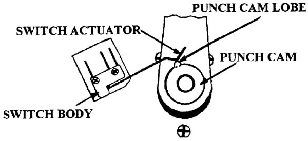
- Make sure Auto/Manual Punch Switch is in "Manual" Punch Mode. Depress "Manual Punch Switch" to cycle machine once. Make sure Punch Actuator is in the peak up position, and turn machine "Off".
- Loosen the Punch Brake Switch (S8) Screws, and raise Switch so the Right Mounting Screw is fully raised in its channel.
- Adjust the left side of Switch until Actuator is parallel with the Switch body as shown in Figure 6-1.
- Tighten both Switch Mounting Screws snugly.
- Loosen the Set Screw in the Punch Cam, and rotate the Cam until it actuates the Punch Brake Switch (S8).
- Tighten Set Screw. Do not over tighten as it is easily cracked.
- Test Punch with a 1/8" (3.2 mm.) stack of paper in both Manual and Auto Punch Modes, and readjust if necessary.
Figure 6-1:
6.2.1 BIND TIMING SWITCH (S13) ADJUSTMENT
- Disconnect Power Cord from the wall outlet.
- Remove the Housing.
- Remove Timing Belt from Bind Motor Pulley and Cam Shaft Pulley.
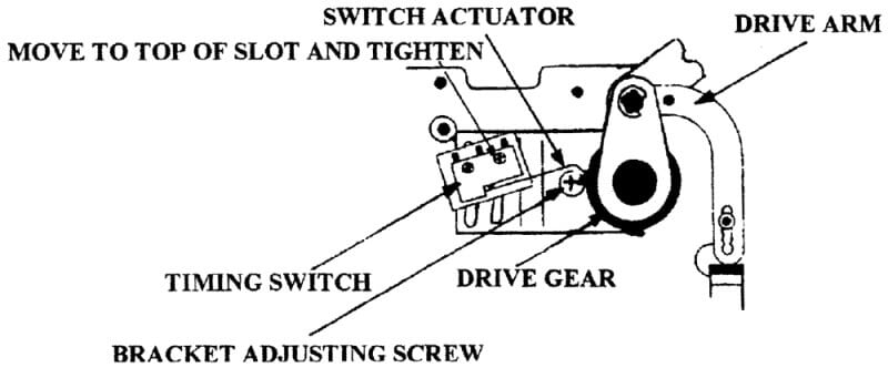
- Manually rotate the Cam Shaft counterclockwise until the Drive Gear Teeth engage the Drive Arm Teeth.
- Continue rotating the Cam Shaft until the Drive Arm drops, and the teeth on the Drive Gear are just past the teeth on the Drive Arm. (Note: Switch must be actuated at this point).
- Loosen the Bind Timing Switch Bracket Adjusting Screw, and adjust the Bracket until it touches the Bearing, and tighten the Bracket Adjusting Screw.
- Loosen the Bind Timing Switch (S13) Retaining Screws, and move Switch (S13) so that Right Hand Retaining Screw is at the top of the Switch Mounting Bracket Slot. Tighten the Right Retaining Screw.
- Make sure Bind Timing Switch (S13) is actuated, and tighten the Left Retaining Screw.
- Replace the Timing Belt, and test the bind timing adjustment on both Standard and Fast Bind Speeds. Minor readjustment may be necessary.
Figure 6-2:
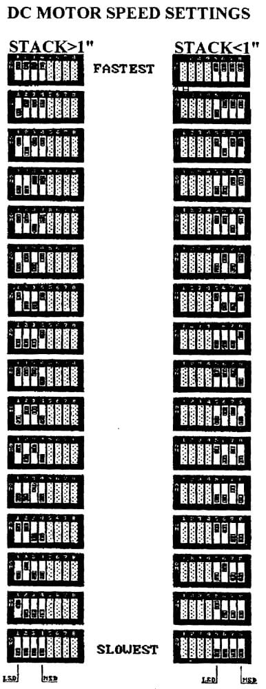
6.2.2 Bind Timing DC Motor Dip Switch Adjustment
Figure 6-2A:
NOTE: Infrared Thermometers are available for testing the Knife Blade temperature on our equipment. The part number is 1722303 (Call 1-866-455-9900 for info), or use a Beaded Thermocouple.
- Check the Knife Temperature.
- If a temperature adjustment is necessary, plug machine in, turn it on, and close tray interlock.
- When machine goes to ready, press >1" and <1" at same time. Display will read "dd" for 2 seconds, and then go to "15" which is the debind time. Press >1" again, and display will read "tt"for 2 seconds, and then go to "05", which is the currently programmed temperature setting.
- To INCREASE the TEMPERATURE, press <1".
- To DECREASE the TEMPERATURE, press "DEBIND".
- Press the >1" to return machine to normal operation.
- Allow 6 or 7 minutes for the temperature to stabilize, and then retest the temperature.
- Make a test bind on both >1" and <1" binding speeds. Readjust temperature as necessary.
- Disconnect Power Cord from wall outlet.
- Remove the Housing.
- Make sure Knife temperature, lateral position, and cutting depth adjustments are correct.
- Bind a 3/8" stack of paper using the "Standard" speed. Inspect the finished product - the rivet head should be flush to .01" above the bottom strip, with no burn marks showing from the Knife Blade.
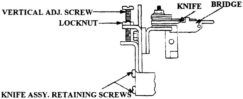
- If adjustment is necessary, loosen the 4 Knife Assembly Mounting Screws attaching the assembly to the Cutter Arm Assemblies.
- Loosen the Left and Right Vertical Adjusting Screws' Hex Nuts.
- Remove the Timing Belt from the Camshaft Drive Pulley, and rotate the Camshaft counterclockwise until the Knife Blade is all the way forward, and at its highest point in the Bridge cutouts.
- Turn the Knife Blade Vertical Adjusting Screws "clockwise" to raise the Blade, and "counterclockwise" to lower the Blade.
**NOTE: A good starting point would be to adjust the Blade level with the Bridge surface. - Tighten the Left and Right Vertical Adjusting Screws' Hex Nuts, and tighten the 4 Knife Assembly Mounting Screws. Reinstall the Belt.
- Run a sample bind to test the Knife Blade vertical position on both "Standard" and "Fast" bind speeds. Minor readjustment may be necessary.
Figure 6-6:
- Disconnect Power Cord from wall outlet.
- Remove the Housing.
- Loosen the 2 Cutting Depth Adjustment Screws.
- Remove the 7 Retaining Nuts and Lock Washers from the Knife Bracket Studs.
- Carefully left off the Knife Plate, and Upper Insulator.
- Carefully lift the Upper Heater up and away from the Knife Blade.
- Remove the Knife Blade, and check the 7 Ceramic Insulators to make sure they are not broken - replace any broken insulators.
- Replace the Knife Blade and/or Heaters, and reassemble in reverse order.
NOTE: MAKE SURE THE "HEAT SIDE" IS FACING THE KNIFE BLADE ON BOTH THE TOP AND BOTTOM.